|

| 1. | Install the Coil Pack Retrofit in a dry location close to the ECU. |
| 2. | Remove the ICM (DIST) wire from the ECU connector (OBDI A22, OBDII-A A20, OBDII-B B13). Insert the Coil Pack Retrofit ICM wire (orange) into the connector cavity in the same place.
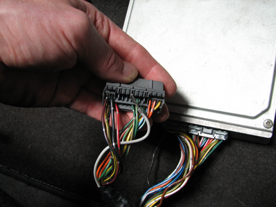 Inserting the ICM pin into the ECU connector |
| 3. | Remove the ALTC wire from the ECU connector (OBDI A16, OBDII-A A19, OBDII-B C2). Insert the Coil Pack Retrofit SYNC wire (white/brown or purple) into the connector cavity in the same place. |
| 4. | Solder the Coil Pack Retrofit power (OBDI A25, OBDII-A A11, OBDII-B B1) and ground (OBDI A23, OBDII-A A10, OBDII-B B2) wires into the ECU power supply close to the ECU connectors. Use soldered connections - do not use 'T taps' or crimps. Do not wire the Coil Pack Retrofit ground wire to the chassis or ECU case.
 CPR wired into ECU power supply |
| 5. | Run the coil pack connectors through the firewall to the distributor. |
| 6. | Connect the Coil Pack Retrofit TACH signal wire to the distributor TACH output (purple wire (harness variation A) or green wire (harness variation B)). |
| 7. | Remove the ICM wire from the coil. |
| 8. | Connect the coil grounds (black with ring terminal) to the stock ground location on the thermostat housing.
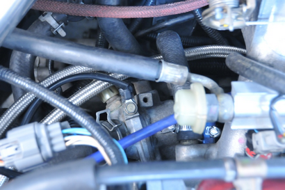 Ground location |
| 9. | Connect the Coil Pack Retrofit power wires (black/white stripe wire (harness variation A) or yellow wire (harness variation B)) to the stock coil power wire (normally black with yellow stripe). |
|